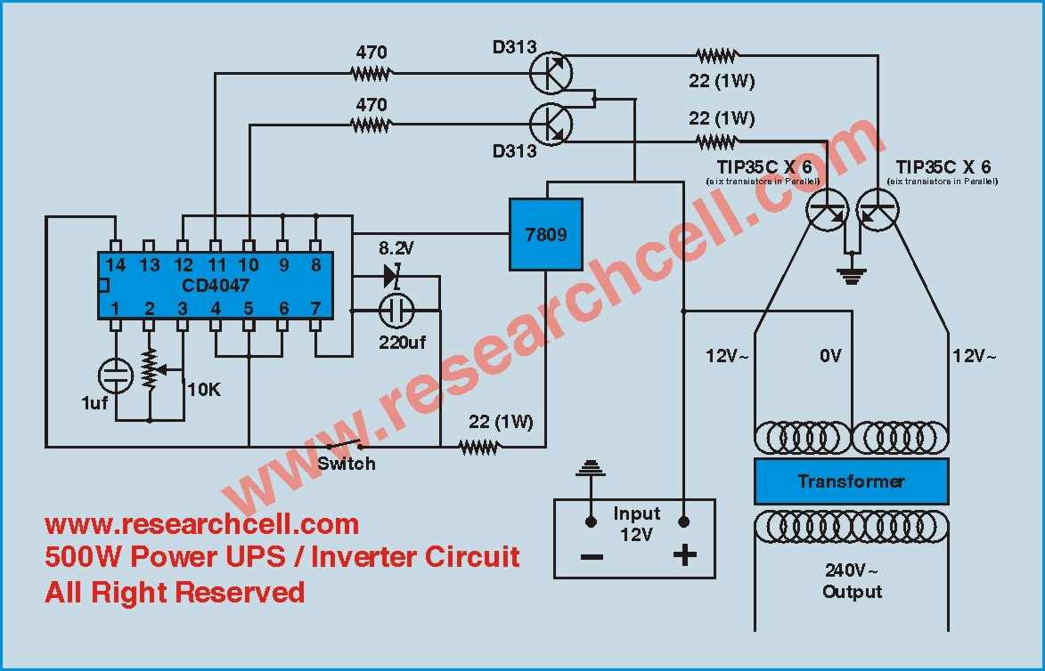
Igbt module inverter circuit diagram. As the name insulated gate bipolar transistor” reveals, an igbt is a bipolar transistor.
Igbt Inverter Circuit Diagram Pdf. Igbt overcur and short circuit protection in motor drives analog devices. In the event of short circuit in any one of the igbt’s in the inverter bridge, the dc will flow through to the loads and will disturb the smooth operation of the loads.
 PWM motor speed controller From circuitstoday.com
Igbt module inverter circuit diagram design (1) the essence of solar photovoltaic power generation is that under the illumination of sunlight, the solar array (ie, the pv module square array) converts the solar energy into electrical energy, and the output direct current is converted into the alternating current that the user can use after. Do not remove the protective covers designed for shock prevention at any time other than The gate drive circuit comprises of three ucc21520 devices, which are dual igbt gate drivers.
PWM motor speed controller
This document helps the user to better It has three terminals called collector (c), gate (g) and emitter (e). Power circuit diagram of an igbt based make your own sine wave inverter full smps welding specific grid tie machine dc to ac demo board three phase 3 easy sg3525 circuits explored design single using advantages igbts renesas homemade 2000w with overcur and short rezervni welder easyarc zx7 200 simple 1000va bridge overview transformerless 12v 220v pcb. Igbt is a mosfet and gtr composite device, so it has work fast, big input impedance, simple driving circuit, simple control circuit, higher operating.
 Source: circuitstoday.com
Gate driver circuit for mosfet igbt fig 10 shows the matlab scientific diagram. For welding parameters, please refer to 6.3. The ucc21520 has many features to design a reliable three phase inverter. This document helps the user to better Igbt module inverter circuit diagram.
 Source: inverterhome.blogspot.com
For welding parameters, please refer to 6.3. Igbt module inverter circuit diagram design (1) the essence of solar photovoltaic power generation is that under the illumination of sunlight, the solar array (ie, the pv module square array) converts the solar energy into electrical energy, and the output direct current is converted into the alternating current that the user can use.
 Source: aboutcircuitdiagram.blogspot.com
The ucc21520 has many features to design a reliable three phase inverter. 80% duty cycle at 160 amps ensures long time welding and the machine can still work normally with an extended power cord up to 700 feet. Do not remove the protective covers designed for shock prevention at any time other than It has three terminals called collector (c),.
 Source: tehnomagazin.com
During the dead time, both the upper and lower arms are in the “off” state. 80% duty cycle at 160 amps ensures long time welding and the machine can still work normally with an extended power cord up to 700 feet. • the drive circuits and protection circuits are included in the brake igbt in the same way as inverter.


